
A Caper Cat is a 14 feet long catamaran designed and built in the 1960’s or 1970’s. I believe that it was designed in Queensland (my home state in Australia) and I would like to hear from someone who knows more – especially the designer if possible.
↑¹²³αβγ¼½¾×
One of the important features of the Caper Cat is its storage capacity in each hull. This makes it ideal for carrying all sorts of things which many similar catamarans cannot do. It is especially useful for camping on the beach and has a history of being used for this purpose.
http://users.tpg.com.au/kkmiller/jessemartin/jesse_martin1.html
In spite of it being very suitable for cruising and laying no claim to being a high-performance machine, I don’t think it has anything to be ashamed of in this department.
Fewer similar catamarans are now being made and, sadly, there seems to be less interest in such sailing (this has not been assisted by local councils who seem to have an agenda of stopping people getting sailing boats onto the beach by putting up obstacles). The age of these boats does not, however, seem to degrade them. It is probably fortunate that fibre glass, aluminium, and good sail cloth were available 50 years ago.
This discussion may also be useful for sailors of other models of catamarans. There are many more Hobie Cats in the world than there are Caper Cats.
Some of the measurements of the Caper Cat follow:
- Length 4.3 meters (14 ft)
- Width 2.3 m (7’6″)
- Weight 115kg (250 lbs)
- Mast Height 6.7m (22 ft) Mast Weight 15 kg (33 lbs)
- Boom length 2.4m (8 ft)
- Mainsail area 10 sq meters (107 square feet) Weight 5.4kg (12 lbs)
- Jib area 3.35 m ² (36 ft2)
- Rudders each 0.9 m (3 ft) deep by 0.25 m (10″) wide Weight of rudders and tiller 13kg
Here are some estimates of mine of the distance from the bow of various points on the longitudinal axis.
- Main spar and mast 1.5 m (5 ft)
- Rear spar 3.4 m (11 ft)
- Stern and rudders 4.3m (14 ft)
- Centre of Mass (or CG) 2.3 m (7’6″) (boat only – no crew)
- Centre Of Buoyancy when level (CB) 2.3m (7’6″)
Theoretical Sailing Performance
I have tried to use the physics of Fluid Mechanics and Sailing Theory to predict the boat’s performance.
Some references are:
- Marchaj C A, Sailing Theory and Practice, Adlard Coles, 3rd edn. 1973
2. Joachim Schult,The Sailing Dictionary, 2nd edition, 1992
3. Editor Michael W Richey, The Shell Encyclopedia of Sailing, 1980
4. Fox R W & McDonald A T, Introduction to Fluid Mechanics, Wiley
5. Roberson J A and Crowe C T, Engineering Fluid Mechanics, Wiley, 5th edn. 1993
6.
https://docplayer.net/53170622-Predicting-the-speed-of-sailing-yachts.html
Peter van Oossanen
( SNAME Transactions, Vol 101, 1993, pp337-397)
Much of that which I have learned has come from the book by Marchaj. I have owned it for over 30 years and can still reread parts of it and learn something. Hence, I don’t claim that it is easy or an “Introduction” – don’t you hate it when text books start with that word and drive you crazy trying to follow them? – but it is well worth adding to your library and reading.
Figures 80 and 224 in my edition (or Fig. 1 in Oossanen, Ref. 6) are very important to show which features we need to know about to truly understand sailing.
(This is also found in Ref. 2 , p102 and Ref. 3, p163)
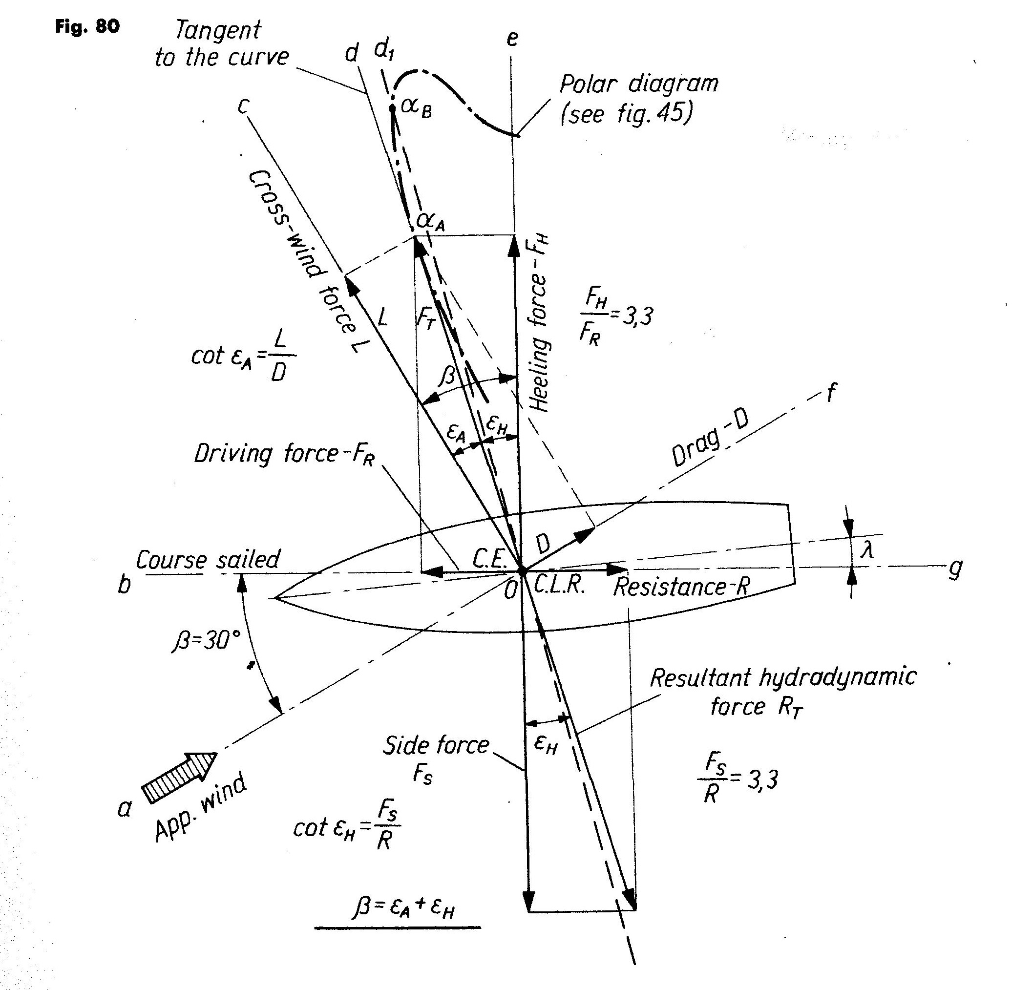
These include:
- Apparent wind strength and direction,
- Strength and direction of the aerodynamic force on the sails; the breaking up of this force into Driving force and Heeling force,
- Strength and direction of the Hydrodynamic force on the hulls and rudders; the breaking up of these forces into Resistance and Side force,
- Leeway angle and its effect on the Hydrodynamic forces;
- Center of Effort (CE) on the sails and Center of Lateral Resistance ( CLR) on hull and rudders.
Mainsail
I have assumed a sail similar to sail in Fig .83 of p.130 of Marchaj. It has a camber of 1⁄10. This sail is equivalent to sail II in Fig. 46 on p.72.
The characteristics of the sail are given below. More information on how the forces are calculated will be given when discussing the boat performance.
Its maximum force coefficient occurs at an angle of incidence of the apparent wind to the chord (roughly, the boom) of 15 degrees, α , and is Ct = 1.55. Another important angle is epsilon, ε , where tan(ε ) = drag/Lift . α – ε is normally positive and is the angle that the direction of the cross-wind force is forward of the perpendicular to the chord of the sail. This angle is forward of the chord because the front part of the sail produces the greatest force and the sail is more curved here just after the luff. This is advantageous because it throws the direction of the force more forward, which is the whole point in driving the boat. I will assume that the main sheet adjusts the sail so that the angle of incidence is always 15 deg. whenever possible. It will not be possible when the wind is coming from abaft because the shroud places a limit on how far the sail can be let out. I assume that the boom cannot be let out beyond 60 deg. It is also not possible, and has to be eased, if it would otherwise capsize the boat , and also if the boat is pointing very close to the wind.
In most cases, I assume that the CE of the sail is about 75 cm (2’6″) behind the luff and 2.6 meters (8’6″) above the boom , which puts it about 3.5 m (11’6″) above the water line.
Sail Characteristics Sail Fig.83 and Fig. 46
| Alpha , α | Ct | Eps, ε |
|---|---|---|
| 5 | 1.05 | 5 |
| 6 | 1.11 | 6 |
| 7 | 1.17 | 6.2 |
| 8 | 1.23 | 6.4 |
| 9 | 1.29 | 6.6 |
| 10 | 1.35 | 6.8 |
| 11 | 1.39 | 7 |
| 12 | 1.43 | 7.46 |
| 13 | 1.47 | 7.92 |
| 14 | 1.51 | 8.38 |
| 15 | 1.55 | 8.84 |
| 16 | 1.55 | 9.3 |
| 17 | 1.505 | 10.3 |
| 18 | 1.46 | 11.65 |
| 19 | 1.415 | 13 |
| 20 | 1.37 | 14.35 |
| 21 | 1.358 | 15.7 |
| 22 | 1.346 | 16.87 |
| 23 | 1.334 | 18.04 |
| 24 | 1.322 | 19.21 |
| 25 | 1.31 | 20.38 |
| 26 | 1.298 | 21.55 |
| 27 | 1.286 | 22.72 |
| 28 | 1.274 | 23.89 |
| 29 | 1.262 | 25.06 |
| 30 | 1.25 | 26.23 |
| 31 | 1.24 | 27.4 |
| 32 | 1.23 | 28.72 |
| 33 | 1.22 | 30.04 |
| 34 | 1.21 | 31.36 |
| 35 | 1.2 | 32.68 |
Jib
The jib has a third the area of the mainsail. There is a school of thought that the foresail is more efficient than the mainsail. In addition, the combination of the two sails increases the effectiveness.
However, the jib is lower than the main and thus encounters lighter winds. I will therefore assume equal efficiency. Most of the time, the combination only needs to be considered so I use the characteristics of the mainsail and use the area of the combination.
I assume that its CE is 6.5 ft above the waterline.
Of course, the jib shifts the combined CE of the sails forward and I assume the new CE is 1’6″ to the rear of the mast in most cases (i.e. close hauled or on a close reach or reach).
If the jib supplies one third of the force of the main, the combined height of the CE above the waterline becomes 10.25 ft.
Hulls
Each hull is divided vertically into 2 sections which I will call the hull (immersed) and the superstructure (normally out of the water). I estimate each hull is 0.194 cubic meters (7 cubic feet) and each superstructure is 0.222 m³ (8 ft³ ). This gives a buoyancy in each hull of about 200 kg (450 lbs) and extra buoyancy in each superstructure of 235 kg (520 lbs).
To estimate the wetted area of the hulls, I assume the hulls are triangular with an angle of 60 degrees at the bottom and calculate using the total weight (boat + crew).
With the total weight W in lbs , the immersed cross-sectional area of each hull is
Ax = (W/64)/(2*LWL) in ft ²
and this is d² *tan(theta), where d is the vertical depth immersed and theta is the half-angle (30 deg) at the bottom.
The immersed distance is then s = d/Cos(theta) and the total wetted area is 4*LWL*s .
This gives wetted area, Aw = sqrt(W*LWL/2/tan(theta))/(2*Cos(theta))
With 2 crewman making a total weight of 620 lbs (280 kg), this gives Aw =50 ft ² (4.6m² ).
The sideways planform area of the hull, Ap (needed for calculating the sideways force on the hull ) , is half the wetted area. (25 ft ² with the above values).
For calculating the “lift” on the hull (i.e. the sideways force generated by a certain leeway angle (required to balance the boat by counteracting the sideways force from the sails)), we need to know the Effective Aspect Ratio. This is pitifully small and I estimate AR as 1 foot immersed divided by 12 feet lengthwise, i.e. 1⁄12. The effective AR can be taken as twice this value – see e.g. Marchaj, pp 276-7. In calculating the coefficient of lift later, it will be seen that this small AR could be a problem.
Rudders
The rudders, of course, steer the boat but also supply much-needed sideways force to augment that from the hull (see Marchaj, pp 350-354). Each rudder has an immersed planform area of about 1.25 ft² and an AR of more than 2.5. This presents a far-superior lifting surface to that of the hull, as will be seen. The tiller gives a mechanical advantage of about 11 when the rudders are fully down. However, if the rudders are raised to almost horizontal to travel over shallow water, this drops to about 3 and steering the boat becomes very tiring. Some Caper Cats have squatter rudders to make running up on the beach easier. These rudders do not need to be released, which can be convenient because having to do so while so much else is happening (e.g in surf) can be difficult. However, given that the lift coefficient of the hulls is so small, it is probably better to have the deeper rudders.
Performance
Yacht performance is discussed in Marchaj, Part III, Section 2, p293 and in Section 4 of Oossanen.
I have tackled this problem by creating an Excel spreadsheet. Velocity Performance Programs (VPP) start with reasonable estimates of velocity and other factors and use successive iteration to improve the parameters until the boat is balanced. In Excel, there is a feature called Goal Seek which effectively solves an equation using this method.
Input
It is necessary to input values to the spreadsheet:
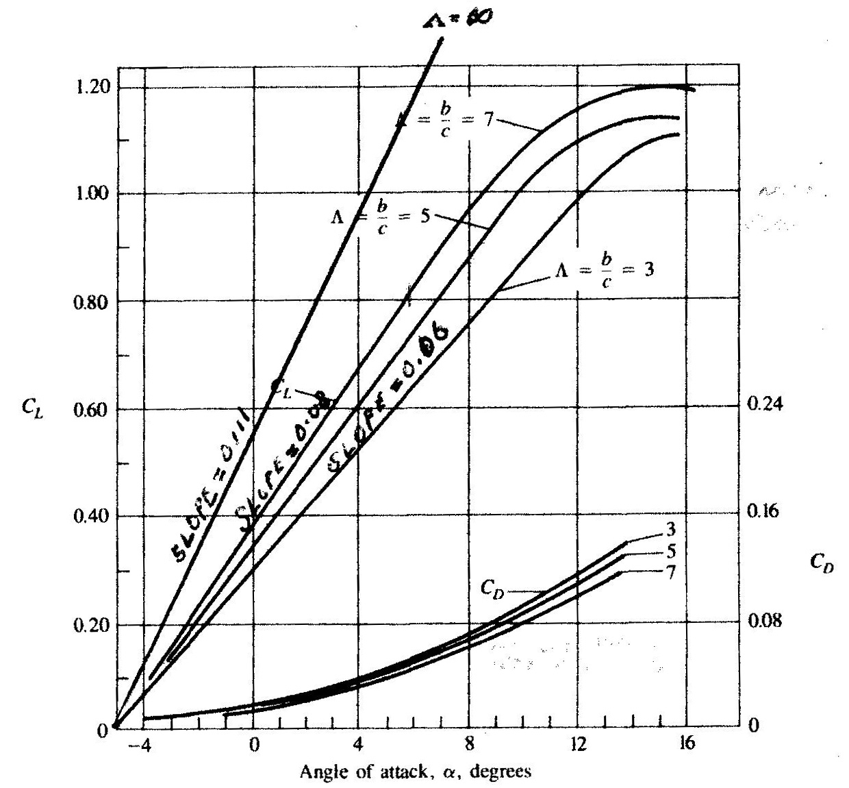
- The various parameters of the boat ; These consist of many of the constants discussed above. The most complex entry is the characteristics of the sail. Refer to Fig 46 and Fig 83 (sail 2) in Marchaj. For each angle of incidence from 5 deg to 35 deg in increments of 1 deg are entered:
- Ct (the coefficient of total force); angle Epsilon (the direction of the force forward of the perpendicular to the chord);
- Hydrodynamic and aerodynamic constants ;
- Speed and angle of the wind to the course of the boat;
- An initial estimate of the boat speed.
How these are used is discussed below.
The dynamic pressure is taken to be 1.00119*v2 where 1.00119 is 1⁄2 *Rho_a , where ρa is the mass density of the air (Marchaj, p45)
For the skin friction coefficient, Cf , I am using Cf =.0040. This is based on a Reynold’s number of 1.7×10⁷ and a reasonably smooth hull (See Marchaj, fig. 148)
Kinematic Viscosity for sea water at 70o F, ν = .0000111 Marchaj, p235 and Ref. 5, TableA.5
Mass density of water Rho_w ρw =1.990
Calculations
Forces on the sail
It is necessary to estimate the strength and direction of the apparent wind. This is discussed qualitatively in Marchaj, Chapter 6. It can be calculated numerically fairly simply by using the cosine rule and this is done, with the results called Va and Beta (β ). (Gamma, γ , is the angle of the true wind to the direction of travel of the boat and Beta (β) is the corresponding angle of the apparent wind).
[ For those who are interested:
Va ² = Vwind² + v ² + 2*Vwind*v*Cos(γ ) ,
and then Cos(β) = (v + Vwind*Cos( γ ) ) / Va , where Vwind = true wind velocity ,
v = velocity of boat , and γ and β are described above. These calculations are done in cells C25, C26, and C27 in the Excel spreadsheet which can be downloaded (see ”Using the VPP” below).]
It is this wind which impinges on the sails and gives the aerodynamic forces on the boat.
The table of values for the sail is then used to choose the optimum angle of incidence ( 15 deg for the most common up-wind directions).
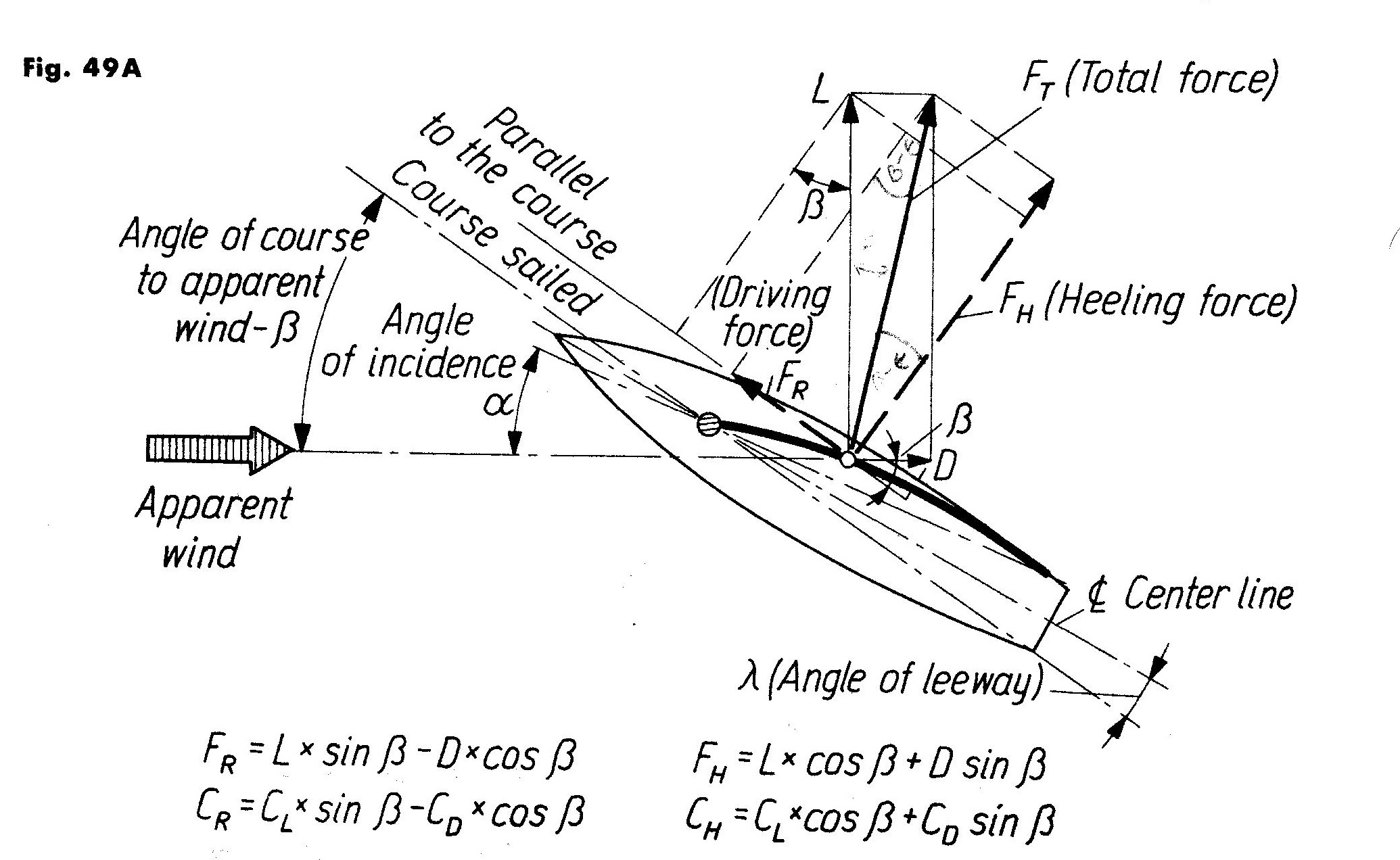
Refer to Marchaj, Fig. 49A, where
L = cross-wind force = Ft*Cos( ε )
D = Drag = Ft*Sin( ε ) and then
FR = L*Sin(β) – D*Cos(β)
= Ft * Sin(β – ε )
FH = L*Cos(β) + D*Sin(β)
= Ft * Cos(β – ε )
Edit Page
Page updated.View PageThere is an autosave of this post that is more recent than the version below.View the autosave
FR is the driving force and needs to be maximised.
So Ct* Sin(β – ε) and Ct * Cos(β – ε) are calculated for each angle of attack (angle of incidence) on the sail and the angle Alpha for which Ct Sin(β – ε) is a maximum is chosen.
The driving force from the sail is then
FR = 0.5*Rho_a * Sa * Ct* Sin(β – ε) *Va ² , where Sa is the sail area.
The heeling force, FH , is similarly calculated:
FH = 0.5*Rho_a * Sa * Ct* Cos(β – ε) *Va ²
It is then necessary to calculate the hydrodynamic resistance of the hull (Marchaj, Part III, Ch 1).
This consists of skin-friction resistance, wave-making resistance and resistance due to leeway (induced resistance). For yachts and dinghies, resistance due to heel is also important but the catamaran has little or no heel so it is ignored.
Skin Friction
This is given by Rf = Cf*Rho_w/2*Aw*v² , where Cf and Rho_w are given above,
Aw is the wetted area and v is the speed of the boat. Note that I am using imperial units (ft/lb/s).
At low speeds and points of sailing other than close-hauled, this will be the predominant resistance. At higher speeds, wave-making resistance becomes very important. I am using
Cf = 0.0040 . For AW being 50 ft² , this gives Rf = 0.199*v² (v in ft/s and Rf in lbs).
Wave-Making Resistance
Refer to Marchaj, pp 245-270, and also, particularly, Fig.149 on p.242 for the International Canoe which I believe is relevant for the Caper Cat.
This is the most complex and difficult-to-estimate resistance (especially for a catamaran). Most of the forces encountered in sailing are proportional to the second power of the velocity (e.g. force on the sail and skin friction) but wave-making resistance involves a higher power (Marchaj, p254: “it can rise to 3rd, 4th, 5th, or even 6th power of the velocity, especially for heavy-displacement keel boats”).
For the International Canoe in Fig.149, with a Skin Friction Coefficient Cf equal to 0.0025 ( hydrodynamically smooth -Fig. 148 ) and a wetted area of 39 square feet, the calculated skin friction resistance Rf is 0.28v2 where v is ft/s. This agrees with the curve in Fig.149.
On the same figure, Wave-making Resistance, Rw, can be taken to be Rw = Cw. vκ , with Cw = 0.00123 and κ = 4 to agree with the curves – “Residual resistance” (Again, v is ft/s.)
Note that when Rf is similarly converted to ft/s it becomes Rf = 0.098*v ² and , for the quoted wetted area of 39 ft² , this implies that Cf =0.0025. The previous graph (Fig. 148) in Marchaj shows that to attain such a low value of Cf requires a very smooth surface. I am being conservative for the Caper Cat and using Cf = 0.0040 .
It is interesting to see at what speed Rf = Rw and it can be seen that, using the above coefficients for the international canoe, this occurs at 5.3 knots. At higher speeds than this, Rw predominates – at least until full planing occurs for some dinghies.
Catamarans have narrow hulls and so the wave-making resistance is fairly small. I am using a power of 4 (called Kappa κ so that it can be varied if desired). In Fig. 155, Marchaj graphs the resistances for the heavy-displacement yacht “New York 32” and inspection of the graph shows that Rw = 0.0118*v5 gives a good fit. So κ is about 5 here and 4 for the canoe. If v is in ft/s, the coefficient becomes 0.000856 , which for Displacement (Delta Δ) of 11.38 tons and length (LWL) of 32.26 feet is 0.44*Δ/LWL(5/2). For the Caper Cat, I am using 0.75*Δ/144/2 since I am using κ = 4. This is 0.00106 when the total weight , with 2 crew, is 620 lbs ( Δ = 0.277 tons). With these values, Rf = Rw at v=13.7 ft/s (8.1 knots).
Induced Drag
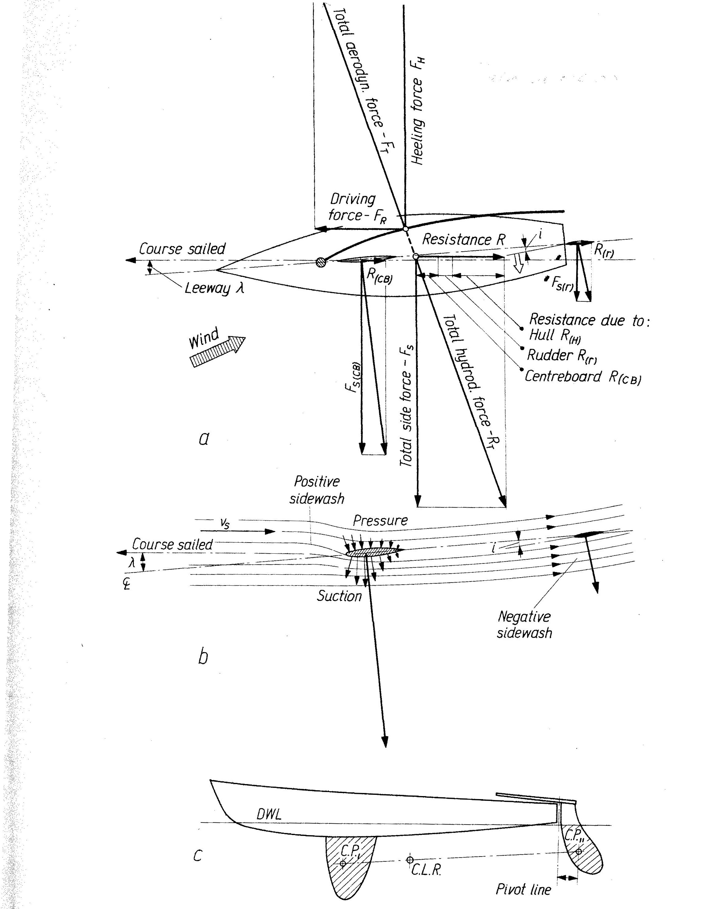
This is also known as Drag due to Leeway. In order to balance the boat laterally, the hydrodynamic lift on the hulls and rudders has to be equal and opposite in magnitude, direction , and point of application, to the force generated by the sails. This force is created by the water hitting the hulls at a small angle λ, the leeway angle, and the rudders at an angle i (see Marchaj, Fig 224 , shown above).
Roberson & Crowe (ref 5), p520 shows that the coefficient of lift ,CL , for an infinite aspect ratio airfoil or hydrofoil is given by
CL = 2πα where α is the angle of attack and is measured in radians. For α measured in degrees, this becomes CL = π ²/90 . α = 0.11 α (α is equivalent to our angle λ ).
Hence, the lifting force FL is given by
FL = CL * S * Rho_w*v ²/2 Unfortunately, our hydrofoils are far from having infinite Aspect Ratio (AR) and CL is greatly reduced. Ref (6), in Section 4.3.3 , gives an expression for the multiplying factor which allows for finite AR . When ignoring certain less-important effects such as viscosity, this factor becomes AR/[2 +( 4+AR2) ½ ] . (Marchaj covers this qualitatively in Fig. 166 as does Fig. 11-23 in Roberson & Crowe (Ref.5) . It is useful to draw in the straight line of slope 0.11 , for infinite AR, in these figures to better appreciate the effect of finite AR. )
I have calculated CL = 2πλ/(1+2/AR) approximately (for large AR) using Ref. 5, p522
Roberson & Crowe Fig. 11.23
The Effective AR of the hulls is twice the AR (Marchaj, p276) and I have taken this to be 0.2 and, with minor adjustments, I have taken CL to be 0.007 λ
Call this CL= a * λ .
The AR of the rudders is about 2.5 and this gives a multiplying factor of 0.48 (i.e “a” equals 0.48*0.11 )and CL = 0.05λ . Fortunately, not all this side force has to be supplied by the hulls, since the rudders can supply a substantial proportion of this force (see Marchaj, Fig. 224 and p 350). If we take the CLR of the hulls to be 5ft from the bow, the CE of the sails to be 6.5 ft and the rudders to be 14ft from the bow, 1/5 of the total side force is supplied by the rudders and 4/5 by the hulls.
The induced resistance coefficient CDi is given by
CDi = CL² /( π *AR) (ref. 5, (11-19) on p522).
For the hulls, this gives CDi = 0.007²/0.6 λ² = 0.0000817 λ²
Let CDi = adi*λ² .
We can now calculate the lift and the induced drag in terms of the (as yet unknown) leeway angle λ .
This allows us to calculate the total drag ( skin friction + wave-making resistance + induced drag due to leeway) and hence the ratio of lift to drag. This has to equal the ratio of lift to drag supplied by the sails and so we get an equation in which the only unknown (for a given velocity of the boat) is λ:
(0.8 FH/FR)*( ½ ρw Aw )*Cf*v ² + (0.8 FH/FR)*Cw*v κ + (0 .8 FH/FR)*adi *(½ ρw Ap) v² *λ² – a * (½ ρw Ap) v²*λ = 0
For a known value of v, this is a quadratic equation in λ and, with the philosophy that no quadratic equation should go unsolved, that has been done . It is probably unnecessary since Excel’s Goal Seek solves iteratively for v later, but it is instructive and gives a good starting value for the iteration .
The quadratic equation is solved in cells E26 to E29 in the spreadsheet.
Having found λ , then FL = a*( ½ ρw Ap)*λ* v² and
Fdrag = ( ½ ρw Aw )*Cf*v ² + adi *(½ ρw Ap)*λ² *v² + Cw.v κ
Velocity Performance Program (VPP)
Here is a link to the spreadsheet which is the VPP.

Velocity and direction of the true wind is input (in cells E13 and A14 respectively) as is also an estimate of the boat speed (in cell C21). It may also be necessary to change the crew weight (in cell F9).
From this is calculated speed and direction of the apparent wind and the strength and direction of the force on the sails. Then the total drag Fdrag is calculated as above.
Fdrag is subtracted from the driving force of the sail, Fr. Call this Fresultant.
Then the Goal Seek function of Excel (Data>What-if Analysis > Goal Seek) is used to set this value to 0 by varying the speed of the boat. This is first done by: Set E36 to 0 by changing C21.
Normally, this will calculate the boat speed (in C21 and C22) which gives a resultant force of 0.
Sometimes, however, maintaining this boat speed would require the crew to be in an impossible position (well outside the boat) in order to balance the boat. In this case, the word “HELP” will appear in cell E44. It is then necessary to use Goal Seek again to set cell D51 to 0 by changing C21. This is explained below in “Capsizing Laterally”.
Capsizing Laterally
One complication is if the crew are unable to stop the boat capsizing laterally (sideways). To check for this, the VPP calculates the capsize moment caused by the force on the sails. The combined CE of the sails is taken as 10.25 ft above the water and this provides the heeling arm. The heeling moment is therefore FH * heeling arm . The restoring moment, to hopefully prevent capsize , is given by the weight of the boat (300 lbs) multiplied by half the width (3.25 ft) plus the weight of crew multiplied by their distance from the leeward hull. The empty boat’s restoring moment is thus 300*3.25 = 975 ft lbs and the crew have to be capable of supplying the remainder of the restoring moment. Thus, the crew have to be a distance of
(heeling moment – 975)/Crew weight. If this distance is greater than 7 ft, I assume that the sheets need to be eased to bring it back to 7 ft.
Maximum Restoring moment = 975 + crew weight * 7 ft lbs
Permissible sideways force on sail , FH , is Maximum Restoring moment / 10.25 lbs .
But FH = .5*RhoaSa Ct* Cos(β- ε) Va2 and this determines Ct Cos(β – ε) , which determines the value of α (which is smaller than the optimum ) which is required to produce the maximum sideways force, FH , permissible to prevent the capsize.
Then FR = .5*RhoaSa Ct* Sin(β – ε) *Va2 . A new Goal Seek then has to be performed using this reduced value of the driving force.
Capsizing Longitudinally
When reaching or running in high winds, FR can be large and cause a large forwards pitching moment. This value is FR*10.25 ft lbs. For example, if FR is 300 lbs, the moment is 3075 ft lbs.
The restoring moment for this situation is provided by Total weight of boat and crew multiplied by the distance between the boat’s CG (Centre of gravity) and CB (Centre of buoyancy). The crew can move the CG back by moving back and the boat will move its CB forward by burying the nose. Just how forward the CB can move before disaster strikes and the boat pitch poles is not known. If the crew has a CG 4′ behind the mast (which seems to be about the maximum if there are 2 crew) , then the overall CG of boat and crew becomes
(‘Weight of Boat ‘* 7.5 + ‘Weight of crew ‘* 9.0)/’Total Weight of boat and crew’ ,
e.g. (350*7.5 + 350*9.0)/ 600 = 9 ft from the bow.
To supply a restoring moment of 3075ft lbs, the distance between CG and CB has to be
3075/600 = 5.125 ft. This means CB has to be at 9 – 5.125 = 3.8ft from the bow. It is doubtful if this could occur without the boat nosediving.
The VPP estimates this position of CB.
The above section may be very relevant for Hobie Cat sailors.
Pinching
A value of α smaller than the “ optimum ” may also be used when close-hauled because of a small value of β . This is because values of α smaller than 15 deg will then produce the maximum value of Ct* Sin(β – ε) . This is the value of α used to find the driving force:
Off The Wind
Another complication is when the direction of the apparent wind is greater than 75 deg from the bow. The boom is then out at its maximum angle (60 deg ) and the angle of attack on the sail is β – 60 . This value is then used for finding the sail force, instead of the optimum of 15 deg which is used for lesser values of β.
Using the VPP
Here is the VPP in the form of the spreadsheet (SS).
Download the Excel spreadsheet as shown above.
Enter the true wind velocity (in knots) into cell E13 and the direction of the true wind into cell A14. Enter an initial estimate of the boat speed ( in knots) into cell C21.
This automatically calculates Fresultant in cell E36 . In the SS, we then need to select cell E36 and click ‘Data’ and then the ‘What-if Analysis’ box and then ‘Goal Seek’.
In the Goal Seek box, Set cell E36 to 0 by changing C21. This should do as requested (i.e., Set cell E36 to 0 by changing C21), but it may determine that, in order to avoid a lateral capsize, the minimum crew distance needs to be greater than 7 feet. If this occurs, “HELP” is displayed in cell E44. Then, a new goal seek has to done by setting cell D51 to 0 by changing cell C21. This recalculates by easing the sheet such that the crew can balance the boat at a distance of 7 feet from the leeward hull.